DL1PRO WP Connections

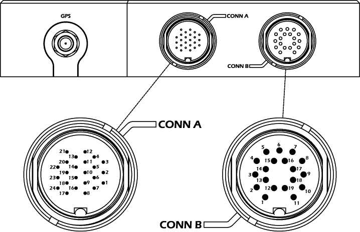
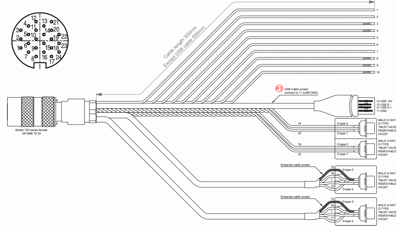
DL1 PRO 24 Way Cable
NOTE: USB lead not used on DL1 PRO. Use USB connector on front of DL1 PRO
| 24 way
| Name
| Description
| Connector or wire colour
|
| 1
| ADC7
| 0-25v 12 bit analogue input
| white
|
| 2
| ADC5
| 0-25v 12 bit analogue input
| black
|
| 3
| ADC10 Out2
| 0-25v input, low side output 0.5A
| red-black
|
| 4
| ADC 9 Out1
| 0-25v input, low side output 0.5A
| gray
|
| 5
| ADC6
| 0-25v 12 bit analogue input
| blue
|
| 6
| ADC8
| 0-25v 12 bit analogue input
| green
|
| 7
| 12v
| 12v supply for serial peripherals
| RS232-1-2 d-type plug pin 7
|
| 8
| 5v ref 2
| 0.5A reference output
| brown
|
| 9
| ADC12 Out4
| 0-25v input, low side output 0.5A
| red
|
| 10
| ADC11 Out3
| 0-25v input, low side output 0.5A
| orange
|
| 11
| GND
| USB GND
| Not connected
|
| 12
| USB5V
| USB 5v
| Not connected
|
| 13
| USB D-
| USB Data -
| Not connected
|
| 14
| CAN1 L
| CAN port 1 low
| CAN[1] d-type plug pin 2
|
| 15
| GND
| Serial port 1 GND
| RS232[1] d-type plug pin 5
|
| 16
| GND
| Serial port 2 GND
| RS232[2] d-type plug pin 5
|
| 17
| RS232 2 in
| RS232 port 2 RX
| RS232[2] d-type plug pin 2
|
| 18
| RS232 1 out
| RS232 port 1 TX
| RS232[1] d-type plug pin 3
|
| 19
| CAN2 L
| CAN port 2 low
| CAN[2] d-type plug pin 2
|
| 20
| CAN1 H
| CAN port 1 high
| CAN[1] d-type plug pin 7
|
| 21
| USB D+
| USB Data +
| Not connected
|
| 22
| CAN 2 H
| CAN port 2 high
| CAN[2] d-type plug pin 7
|
| 23
| RS232 1 in
| RS232 port 1 Rx
| RS232[1] d-type plug pin 2
|
| 24
| RS232 2 out
| RS232 port 2 Tx
| RS232[2] d-type plug pin 3
|
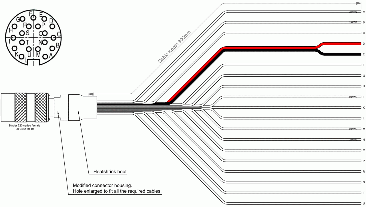
DL1 PRO 19 Way Cable

| 19 way
| Number
| Name
| Description
| Connector or wire colour
|
| A
| 1
| ADC1
| 0-25v 12 bit analogue input
| black
|
| B
| 2
| ADC2
| 0-25v 12 bit analogue input
| brown-black
|
| C
| 3
| GND
| Sensor ground
| red-black
|
| D
| 4
| 12v
| System power 9-24v
| figure-8 cable black-white
|
| E
| 5
| GND
| Power ground
| figure-8 cable black
|
| F
| 6
| High level RPM
| 1kHz HT input
| orange-black
|
| G
| 7
| RPM_GND
| See Connecting RPM
| yellow-black
|
| H
| 8
| GPS LED
| Active low GPS LED driver (20mA
| green-black
|
| I
| 9
| 5v ref 1
| 0.5A Reference output
| blue-black
|
| K
| 10
| Frequency in 3
| 5-12v input >2khz max (100k pulldown)
| grey-black
|
| L
| 11
| Frequency in 4
| 5-12v input >2khz max (100k pullldown)
| white-black
|
| M
| 12
| ADC4
| 0-25v 12 bit analogue input
| brown
|
| N
| 13
| ADC3
| 0-25v 12 bit analogue input
| red
|
| O
| 14
| Power LED
| Active low Power LED driver (20mA)
| orange
|
| P
| 15
| Low level RPM
| 5-15v Trigger - ECU or Tacho use
| yellow
|
| R
| 16
| Logging LED
| Active low Logging LED driver (20mA)
| Green
|
| S
| 17
| Status LED
| Active low Status LED driver (20mA)
| blue
|
| T
| 18
| Frequency in 1
| 5-12v input >2khz max (100k pullldown)
| gray
|
| U
| 19
| Frequency in 2
| 5-12v input >2khz max (100k pullldown)
| white
|


