CAN Interface Configuration
Description of Operation
The configuration of the interface module is performed using the CAN configuration software, which is a standard part of the Race Technology V7 software installation. This can be found in the configuration section of the installation. When started, the CAN Configuration software will look like this:
RT message
These are the available output messages. All output messages must be scaled for a value from 0-65535 for unsigned and -32768 to 32767 for signed values. Output messages are split in to the following groups
    Temperatures (25 channels)     Time (12 channels)     Percentages (31 channels)     Frequencies (4 channels)
With the exception of the time channels, all channels are of exactly the same data format, so can easily be used for any other function.
CAN ID length
There are two CAN addressing modes in common use; 11bit and 29bit addressing. This field must be set to the same type of addressing mode as the messages to be decoded are using. If the addressing modes do not match, messages will not be decoded, even if the address is otherwise a match.
CAN ID
Selects the CAN ID which will be used to receive the message. This may be either a decimal value or a hexadecimal value. Hexadecimal values are specified using the prefix "0x". For example, the (hexadecimal) channel ID 500h may be entered as either 0x500 or 1280 in the CAN configuration software.
Filter location
It is possible to use one byte of the message as a filter, when a byte is selected for the filter location, only messages which have the correct filter value will be used.
Filter value
Used in conjunction with filter location to enable message reception only when the byte specified in filter location matches this value.
Start bit
The location of the first bit of the data to be received. Ranges from 0-63
Length
Total number of bits in the message, from 1-32
Value type
Select signed, unsigned or floating point. Floating point values are as defined in the IEEE754 Format,
Byte order
Select from the following byte orders:
    Intel Standard   Motorola forward MSB     Intel Sequential   Motorola sequential     Motorola forwared LSB         Motorola backward
For more information on these formats, see the appendix Byte Ordering.
Scale factor
A factor by the output value will be divided before being sent out through the serial port
Offset
A value which is added to the output value before it is output (scale factor is applied before offset)
Loading and saving files
From the file menu you can select to load or save data files
Enable OBDII mode
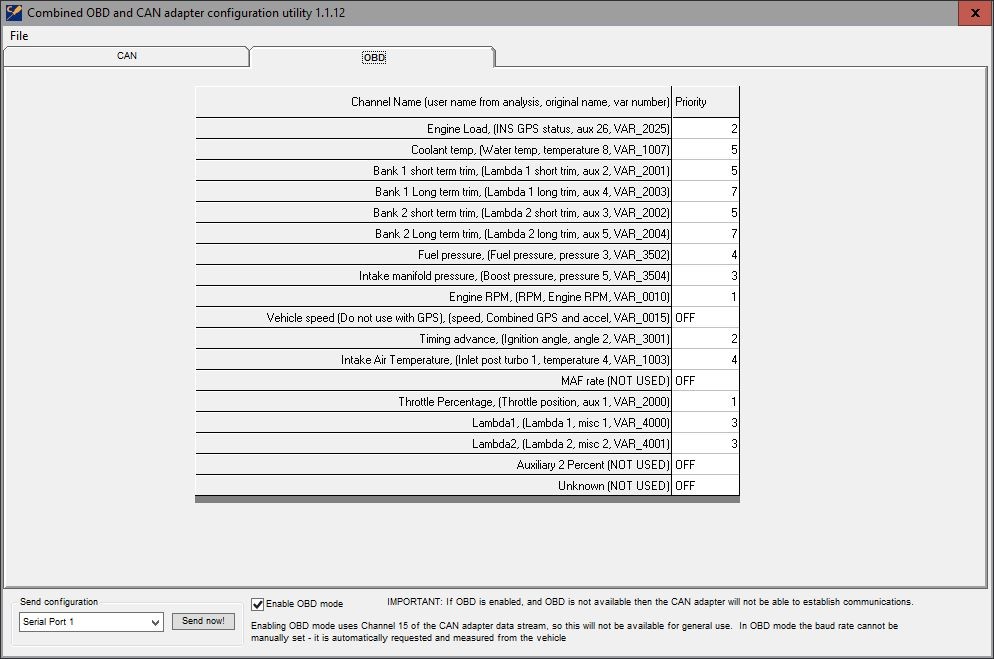
The OBDII mode will only work with vehicles equipped with CAN based OBIDII interface, the interface needs to be ordered from Race Technology as an OBDII version. When enabled the OBDII tab can be selected from where the priorities of the different messages can be set:
Priority 1 messages are requestsed twice as often as priority 2, which are requested twice as often as priority 3 and so on. Turn off channels which are not being used to increase the useful data coming through from the interface.


