|
Call me back |
|

You are here: Website » Knowledge base
|
GPSTheoryAndBackground / LeverArmOffsetLever arm offsetLever arms offset refers to the mathematical operation of shifting a measurement in one location to another. In the case of the SPEEDBOX INS system, this typically means measuring all the vehicle "states" on the roof, and shifting them to the centre of gravity (CoG) of the vehicle, or alternatively some other measurement point, such as the contact point between the tyre and road. In this case vehicle states refers to attitude (roll/pitch/yaw), acceleration, velocity and position. Whilst mathematically it is perfectly possible to shift the measurements from any location to any other, in practice there can be issues in doing so. The main issue is the magnification of rotational (attitude) noise, both gyro noise and vehicle vibration, into linear noise by the lever arm. For this reason, in a practical engineering environment, it is good practice to keep the lever arm distance to a minimum. For example if you want measurements for the centre of gravity of the vehicle, it makes sense to mount the INS system directly above this point. Note that whilst we refer to the operation of mathematically shifting the measurement from one location to another as a lever arm offset, other manufacturers refer to the same operation as "point of interest" or "measurement transformation". All these operations are mathematically the same and are just differences in terminology. Further in all cases be aware of the sign convention. For Race Technology equipment, the lever arm is always specified as a vector from the actual measurement location (the INS antenna unit) to the desired measurement location (typically vehicle CoG). This vector is positive when going forward, rightwards and downwards from the measurement location. This sign convention is consistent with that of local NED velocities. Example 1: the INS antenna is mounted on the roof towards the rear of the vehicle, 1m above the CoG and 1m behind the CoG. Specify the lever arm from antenna to CoG as +1m ahead and +1m below. Example 2: the INS antenna is mounted on the roof towards the front of the vehicle, 1m above the CoG and 1m ahead of the CoG. Specify the lever arm from antenna to CoG as -1m ahead and +1m below. Of the measurements we need to shift, some are far easier than others. From simple to complex and problematic: Altitude: assuming that the vehicle is a rigid body then the altitude at any point on the vehicle is the same and there is no action needed. Position: this is trivial, the system simply takes the measured position and attitude and corrects with the lever arm offsets directly. Although in theory some position noise could be introduced through attitude noise, in practice this is negligible and the output position signal is not degraded in any way. Velocity: shifting velocity is mathematically relatively simple, but in practice it introduces noise into the output primarily due to gyro noise, but also through mechanical vibration. Typical extra noise for a lever arm of 1m horizontally + 1m vertically is in the region of 0.01kph. Acceleration: shifting acceleration is mathematically rather more complicated than velocity, but the result is similar to with velocity, but even more pronounced. The reason for this is that body acceleration is the differential of body velocity. Acceleration is hence particularly affected by high-frequency gyro noise when a lever arm is used. Typical extra noise for a lever arm of 1m horizontally + 1m vertically is in the region of 0.1g.
Derived variables or states:Direction of travel variables, including gradient: Since these are calculated from the vehicles velocities they are subject to the same problems as velocity. Slip angle: This is calculated as the difference between the yaw and heading and, as above, subject to the same problems as velocity. Distance: This is calculated by integrating velocity, and whilst the velocity appears to be noisy with long lever arms, it is still mathematically correct, and the process of integrating very largely negates the effects. In practice distance is very robust to lever arm offsets.
Practical examples:Static test, engine offIn this test the INS system was fitted to a vehicle roof, which was parked without the engine running to minimise vibration. The results below are for 3D speed and longitudinal acceleration. In all cases the results are given for a lever arm offset of 1m horizontally backwards and 1m vertically down. From the graphs it can be seen that the effect on the speed is to increase the apparent noise by approximately 0.01kph, and the effect on the accelerations is to increase the apparent noise by approximately 0.02g (1 sigma). Since there is no mechanical vibration in this test we can deduce that the extra noise is solely due to the gyro rate noise coupled with the lever-arm. With no lever arm and for the same test the noise on the accelerometers are rest is below 0.001g (1 sigma) and 0.003kph (1 sigma). On the graphs below, the no lever arm case is on car, and with lever arm black.  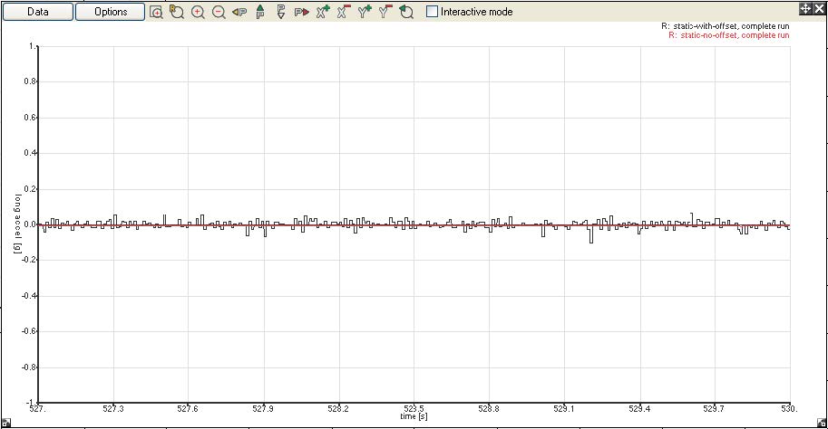
This test shows that whilst the noise is only marginally increased on the speed, it is very significantly increased on acceleration. There is no fix for this effect as it is due to the noise on the gyro sensor signal inherent to MEMs type devices, the only way to reduce it impact is by applying some filtering to the acceleration data. With the specified lever arm applied and full bandwidth, acceleration noise is 0.020g. Limiting the bandwidth to 20Hz gave 0.011g, 10Hz gave 0.006g and 2Hz bandwidth gave 0.002g. In all cases this is the 1 sigma noise.
Driving a passenger car on a standard highway.The same set up as above was repeated, but whilst driving on a normal highway. From the graphs it can be seen that the effect is to increase the apparent noise on the speed by approximately 0.025kph (1 sigma), and 0.13g (1 sigma) on the longitudinal acceleration. For the same test the results with no lever arm where 0.075kph (1 sigma) and 0.04g (1 sigma). In this case we can see the same trend for acceleration, adding a lever arm adds significant noise to this signal. In the case of speed, it is more complex. The 1 sigma speed actually decreases in the case where we have added a lever arm. This effect was unexpected, but looking at the data its clear that lower frequency noise on the non-offset speed output is not actually noise – this is the real pitching of the vehicle roof relative. When we add a lever arm we are closer to the pitch centre of the vehicle and this low frequency information is reduced. Put simply, as we go over minor bumps on the road the speed at the roof changes more than the speed at the pitch centre of the vehicle. Because of this effect it is difficult to say what noise the lever arm has added to speed, but a reasonable estimate would be something in the range of 0.01kph to 0.02kph.  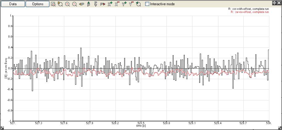
Appropriate IMU mountingThese first results were taken above were from a passenger car, the roof on this car (a Mercedes R class) was slightly curved and so fairly rigid. If you pushed down on the steel at the mounting location there was very little deflection. These results could be considered “typical” To demonstrate the importance of the mounting position, 2 further tests were carried out on a commercial van, a Mercedes Vito. This vehicle was chosen as its roof was relatively flat, and hence less rigid. The exact same test was done as above, but at with the IMU assembly at 2 locations. In the first test it was mounted centrally on the roof, where the roof appeared most flexible, and secondly at the front of the roof where the roof appeared to be most rigid. The results are shown below: 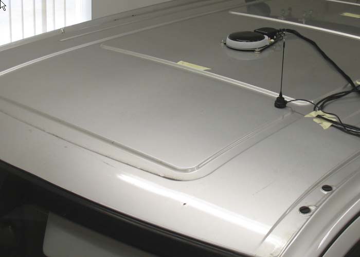 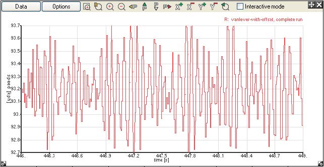 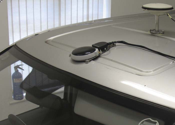 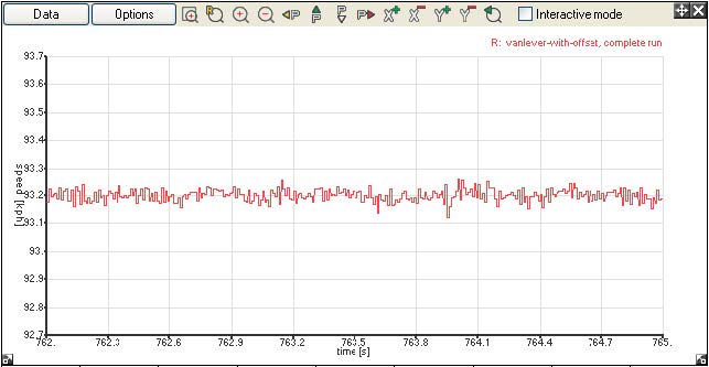
For this test the approximate noise with the antenna in the middle of the roof panel was 0.25kph (1 sigma), and at the front of the roof 0.02kph (1 sigma). Whilst these results could be considered at the “extremes”, it clearly shows how important the mounting location is when a lever arm is needed. Further tests shows similarly good results if the INS was mounted on near the left and right hand side of the roof where it was also more rigid.
Further information.From the discussion above, a common question is: “if the lever arm offset introduces problems, then why not separate the GPS antenna and IMU and locate the IMU at the point where you want the measurements”. In fact in some situations this is the best solution, but there are some very significant downsides:
In conclusion:All these results are for an example lever arm of 1m horizontal and 1m vertical. If the lever arm length was doubled, then the apparent noise would also double, and vice versa. These results are for a normal section of public highway (the A610 dual carriageway) local to the Race Technology office. If the car was driven on a smooth test track then the effect would be less pronounced, on a rough road then the effect would be magnified. From the above results it is very clear that, although mathematically correct, the lever arm offset does appear to degrade the velocity by a small amount, but acceleration to a much greater level. There is no complete fix for this, however there are 3 simple practical steps that can be taken to minimise the effect:
For all temporary installations, typical of automotive testing it is considered better to mount the system on the roof and move the measurement to the required location using the lever arm offset. Only in rare cases, where very low noise accelerations are needed to the shifted location should separating the GPS antenna and IMU be considered. For permanent installations, then it might be preferable to locate the IMU and GPS antennas at different locations, but this come at the expense of greatly increased the installation time, further in this case, care is required to ensure the accuracy of the results. |