Map analogue input voltages from a DL1 MK2 as sensor values
To configure the DASH2 PRO to display DL1 sensor info, the analogue data which comes from the serial port on the DL1 needs to be read by the DASH2PRO, and then suitably scaled on to the correct channel for display and/or storage. This is how it is done.
The DL1 will only output analogue voltages on the serial port, these come out as analogue channels 1-8. To simply display these on the DASH2PRO just map the channels to come from the serial port and select them to be displayed. To convert the channel to a channel you can use, requires the use of the variable source menu and some user defined equations.
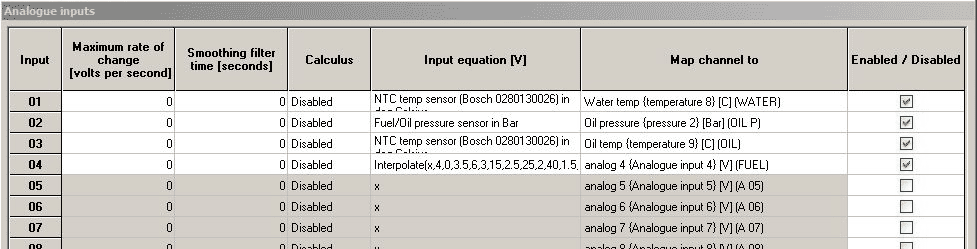
The DL1 Mk2 will only output messages on analogue channels 1-8, i.e. analogue 1 = Analogue 1 and so on. As such it is important that none of the internal analogue inputs on the DASH2PRO are already mapped to these channels. By default the fuel level is mapped to analogue channel 4. This should be changed to channel 9.
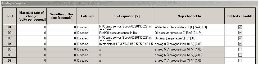
This shows the default configuration, with fuel on channel Analog 4. Change this to 9. If an equation has been set up for channel 4 then copy and paste it across to 9.
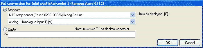
For this example we assume that a temperature sensor which we wish to map to Inlet Post Intercooler 1 channel is attached to analogue input 2 on the DL1 MK2.
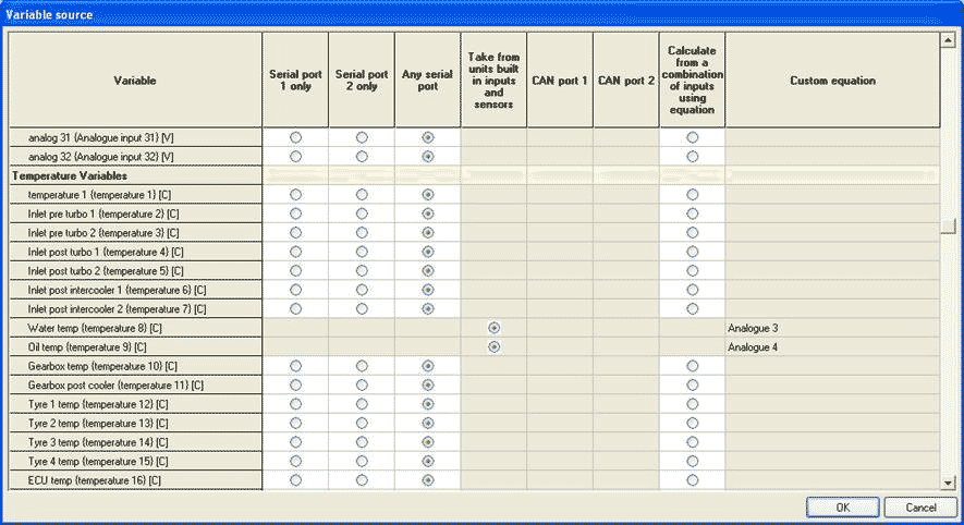
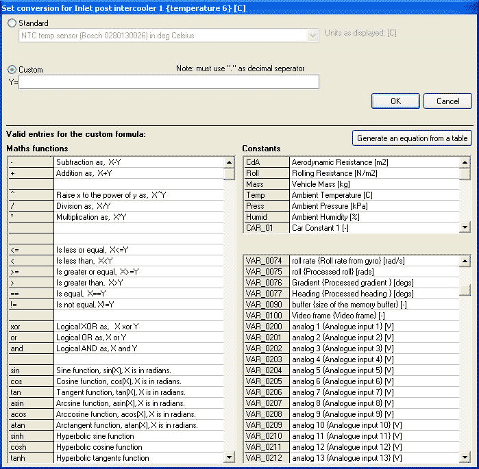
Select the variable source option in the configuration software.
For each of the channels there is the option to calculate from a combination of inputs using equation. Tick this box and then click on Custom equation. This is where the equation is entered to convert the information from the raw voltage reading from the DL1 and to tell the DASH2PRO which channel to read the voltage from.
The list of RT equations for the different sensors can be found here:
First off click the bullet selector for the “Use equation” option and click in the box next to it on the right to open the equation menu.
Either use one of the standard sensor types if applicable, and select the relevant analogue channel from the DL1, or click on Custom
In the bottom right menu channel codes next to each variable, these are the codes we need to use in the equation, i.e. Analog 2 is code VAR_0201.
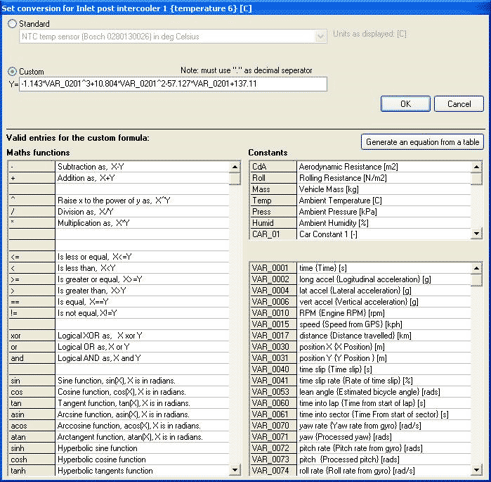
For our theoretical air temperature sensor the equation we need to apply is --1.143*input^3 + 10.804*input^2 -57.127*input + 137.11
To put this in as a custom example, anywhere 'input' is written it must be changed to the variable to be used, in this case VAR_0201
-1.143*VAR_0201^3+10.804*VAR_0201^2-57.127*VAR_0201+137.11
We now have the voltage from analogue input 2 on the DL1 mapped to a temperature channel on the DASH2PRO, this can be displayed on the screen, have the units changed for the display, be used for alarms or logged on the memory card. The same theory applies for any other type of sensor.