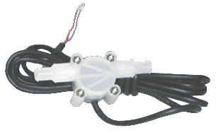
Fuel Flow Sensor
Small, plastic fuel flow sensor that produces a pulse output, the frequency of which is proportional to the flow rate through the device.
Please note, the formation of vapour should be minimised by fitting the sensor between the fuel pump and carburettor, but before any pressure regulator. The device should be mounted vertically if vapour is likely to form. Extreme care must be taken when modifying the fuel supply on a car!
Maximum safe working pressure = 10 bar
Technical Data
| Jet size | 1mm | 2mm | 3mm | 4mm | No jet |
| Flow (1/min) | 0.05 - 0.5 | 0.05 - 1.5 | 0.15 - 4.5 | 0.18 - 6.5 | 0.2 - 10 |
| Linearity % FSD | 2.0 | 2.0 | 1.5 | 1.5 | 1.0 |
| Typical FS Frequency Hz | 142 | 175 | 260 | 230 | 235 |
| Approx. 'K' Factor | 17000 | 7000 | 3500 | 2100 | 1420 |
| Max. Viscosity cSt | 10 | 20 | 30 | 40 | 50 |
| FS Pressure drop | 1 Bar @ 1cSt | 1 Bar @ 1cSt | 1 Bar @ 1cSt | 1 Bar @ 1cSt | 1 Bar @ 1cSt |
| Temperature range | -25 to +125oC | -25 to +125oC | -25 to +125oC | -25 to +125oC | -25 to +125oC |
| Repeatability | ±0.25% | ±0.25% | ±0.25% | ±0.25% | ±0.25% |
| Sensor to sensor variation | ±5% max. | ±5% max. | ±5% max. | ±5% max. | ±5% max. |
| Supply voltage | 4.5 to 24Vdc | 4.5 to 24Vdc | 4.5 to 24Vdc | 4.5 to 24Vdc | 4.5 to 24Vdc |
| Current consumption | 10mA (typical) | 10mA (typical) | 10mA (typical) | 10mA (typical) | 10mA (typical) |
| Output | Open collector (10kΩ internal pull up) | Open collector (10kΩ internal pull up) | Open collector (10kΩ internal pull up) | Open collector (10kΩ internal pull up) | Open collector (10kΩ internal pull up) |
| Output low | 100mV max. | 100mV max. | 100mV max. | 100mV max. | 100mV max. |
| Rise & fall times | 2μS max. | 2μS max. | 2μS max. | 2μS max. | 2μS max. |
| Wetted materials | PVDF, sapphire & Viton. Ceramic magnet | PVDF, sapphire & Viton. Ceramic magnet | PVDF, sapphire & Viton. Ceramic magnet | PVDF, sapphire & Viton. Ceramic magnet | PVDF, sapphire & Viton. Ceramic magnet |
Fuel flow (Litres/second) = x / K factor
Installation
The sensor come with 3 wires, the red wire should be connected to the 5v output from the Data Logger Units, the black wire should go to the ground connection and the white wire should go to one of the frequency inputs

