DL1 Configuration for VIDEO4
IMPORTANT: For full compatibility with the VIDEO4, the DL1/2 must be running firmware version 25 or later. If this is not the case the remote start/stop and add lap marker will not work.
When using the DL1/2 and VIDEO4 together, then the DL1/2 simply acts as a source of data for the VIDEO4 - there is no need to access it during normal operation. The DL1/2 doesn’t even need a CF card to be inserted, it just needs to be powered and connected to the VIDEO4 with the supplied serial lead. In this configuration the VIDEO4 does all lap timing, can be controlled remotely from a DASH1/2/3 just as the DL1/2 can be and can be configured for automatic start/stop just as the DL1/2.
To ensure correct operation the DL1/2 must be configured correctly so it sends the correct information to the VIDEO4. To do this you need to use the DL1/2 configuration software:
- Start up the DL1/2 configuration software
- Make the required settings as described below
- Save the configuration onto a CF compatible with the DL1. This card must be formatted as FAT16, and the file must be stored in the root directory
- With the DL1 powered up, insert the CF card into it, the DL1 will read this configuration information and configure itself
- Note that the DL1 will store the configuration information on the internal flash, there is no need to reconfigure it before each use.
The DL1 MUST be configured to:
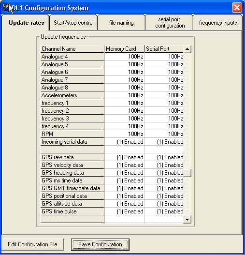
1. Output all analogue and frequency channels at 100Hz to the serial port
2. Enable all GPS data to be output over the serial port (without this the lap timing will NOT work)
3. Enable incoming serial data, and all GPS data to the serial port
4. Enable lap beacon data to the serial port
5. The Autostart/stop control can be left as the default settings as these have no effect when no CF card is used
6. The file naming tab can also be left with all the default values as again, these are only used when the DL1 is used to log data to the flash card
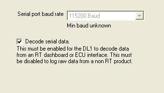
7. On the serial port configuration tab you must set the serial port baud rate to 115200, and tick the box that says “Decode serial data”
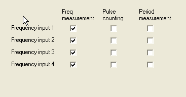
8. On the frequency inputs tab, please tick all 4 boxes for “Freq measurement” and leave the boxes for “pulse counting” and “period measurement” unticked.
Connection to Other RT products
All current RT hardware uses a standard data protocol that allows anything to be connected to anything else in almost anything else in almost any combination. Diagrams of how to connect together the most common combinations are illustrated here.


