<< back to the main configuration page
Analogue Inputs
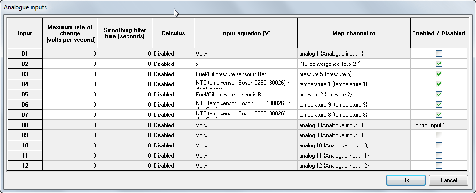
From the configuration software, click on the Analogue inputs box to set up the analogue input channels on the DL1 CLUB:
Analogue input channels on the DL1 CLUB can be configured to be mapped directly through to temperature, pressure, angle, or auxiliary channels.
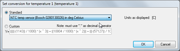
To set up an analogue input for use with a standard sensor, simply select the channel the data should be routed through to, such as Water Temp, then click on the Input Equation box and select the standard sensor from the drop down list:
For non-standard sensors the input equation can be entered manually. By clicking on Custom the list of maths functions will be displayed. Equations can be entered using X as the input value, so a typical equation might be:
-1.427*x^3+10.804*x^2-57.127*x+127.11
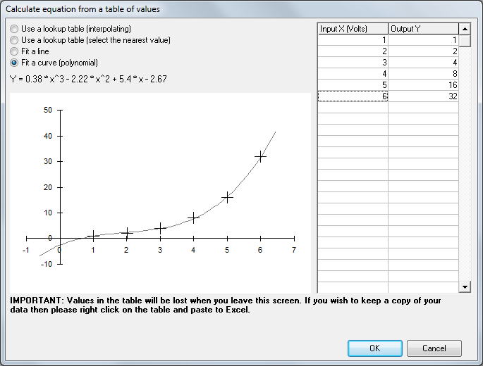
If required, data can be input from a table, by selecting Input Data From a Table the input voltages from the sensor and output readings can be entered.
There are four options for how the input and output data are used:
Use a lookup table (interpolating)
This draws a straight line between each point in the data and uses this to calculate a value.
Use a lookup table (select the nearest value)
This option will pick the input voltage on the table which is closest to the current voltage and give the corresponding output. Particularly useful for gear indication
Fit a line
This will put a simple straight line through the data points and fit the data as well as it can.
Fit a curve(polynomial)
This will fit a fourth order polynomial to the data, as shown in the example above.
Input filtering can be applied with either a rate of change filter, which will limit the change in input voltage to a certain number of volts per second. Alternatively smoothing can be applied by smoothing the input values over a period of time [seconds]
Calculus can also be applied to either integrate or differentiate the input with respect to time.
When adding new sensors, start with the lowest number analogue input and work upwards. The inputs at the top end can be used for other purposes.
Channel value limits
Please consider that different channel types expect certain units and have a limited range in terms of the values stored. Attempting to store values outside of these ranges will cause errors. The allowable limit of values and the correct units for storage in each channel type are as shown below:
| Channel type
| Range
| Resolution
| Unit
|
| External temperature channel
| -3276.8 – 3276.7
| 0.1C
| C
|
| External pressure channel
| 0 - 65535
| 1mB
| mB
|
| External frequency channel
| 0 - 6553.5
| 0.1 Hz
| Hz
|
| External time channel
| 0 - 65535
| 1ms
| ms
|
| External auxiliary (percentage) channel
| -3276.8 - 3276.7
| 0.1%
| %
|
| External angle channel
| -3276.8 - 3276.7
| 0.1o
| Degrees
|
| External Miscellaneous channel
| 0 - 655.35
| various
| -
|
| Yaw / Pitch / Roll rates
| -327.675 – 327.68
| 0. 01o/sec
| Degrees/s
|
| Accelerations X/Y/Z
| -127.996 – 127.996
| 1/256g
| g
|
| Voltage
| 0-65.535
| 1mv
| v
|
Next >> Frequency inputs