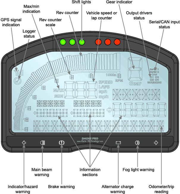
GPS signal indication
The antenna symbol will show whenever GPS data is being recieved, either from the internal GPS receiver or an external data logger, four bars of signal strength are required for lap timing to operate. This signal stength is based on the GPS positional accuracy figure from the GPS receiver.
Logger status
The tick symbol will appear when either an external data logger is logging data or the internal optional logging is activated.
Max/Min indication
The relevant indicator will light whenever either the maximum or minimum values are being displayed.
Rev counter scale
The numbers on the scale can be customised to read values between 0 and 19 for up to 19 000 rpm.
Rev counter
Usually used to display the engine speed, along with a peak hold indicator, this scale can also be configured to display any other variable.
Shift lights
In standard mode these three green and three red LEDs are used as shift lights to show when to change gear, with the advanced options it is possible to set a different low temperature set of RPM thresholds, to display a performance indicator or to have different settings in different gears.
Vehicle speed or lap counter
Depending on the mode either displays the vehicle speed in kph or mph, from GPS or wheel speed sensor, or displays the current lap number or number of laps remaining.
Gear indicator
Configured either based on gear ratios, engine speed and vehicle speed, or to come from an external sensor channel, this shows the currently selected gear.
Output driver status
If an output driver is currently active the relevant section will light.
Serial / CAN input status
When data is being received from either serial port or from the CAN ports the relevant section will light.
Information sections
These are the main display sections where the user configured information is shown, warning data is also shown in these areas.
Indicator / hazard warning
The left and right indicator warnings light whenever 12v is applied to the relevant input wire, the brightness of these inputs changes depending on whether or not the sidelights are turned on.
Main beam warning
Lights when 12v is applied to the warning input
Brake warning
Lights when 0v is applied to the warning input
Alternator charge warning
When the alternator is not charging this symbol will light up.
Fog light warning
Lights when 12v is applied to the fog warning input wire
Odometer / trip warning
The bottom display section is usually used for displaying the odometer and the trip counter readings, but is also used for menu navigation and warning displays

