|
Call me back |
|

You are here: Website » Knowledge base
|
R41NoiseEmissionsTestSystem / OverviewAndFeaturesOverview And FeaturesPass-by Noise Testing System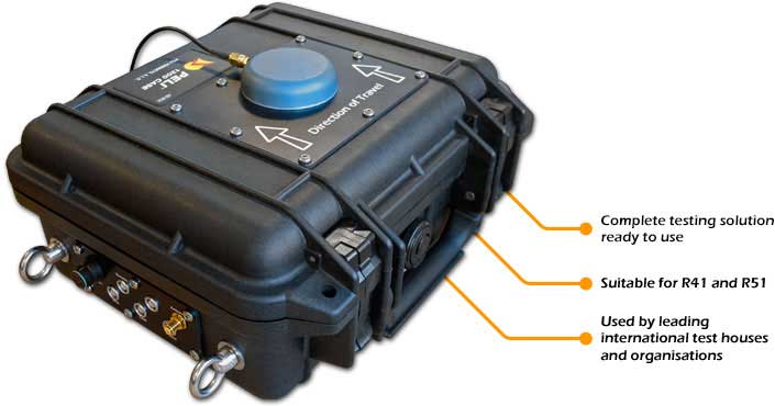 Click here to download a PDF product information sheet We offer complete pass-by (drive-by) noise testing systems suitable for both cars and motorcycles. The systems are based around a compact, customised Peli case that mounts on/in the vehicle and a trackside PC and sound meters. With a wireless data link between the vehicle mounted kit and the trackside PC. All data and results are recorded to the trackside PC in the Performance Monitor software, and test results and data are fedback to the vehicle mounted display for instant feedback.
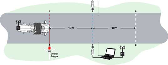 Quick and easy installation for both car and motorbike offering RPM data directly from cars OBD connector as well as direct CAN inputs and sensor inputs for motorcycles. The base station set up is quick and easy with only the optical trigger and the sound-meters required. Passing the optical trigger starts the test at point AA, with the system automatically measuring the distance to P-P and B-B, with the relevant speed, RPM and sound measurements transmitted to be displayed/recorded on the base station. This application note describes the test equipment and performance monitor software used in SPEED80X R4 Drive-by-noise system. The system produces results to comply with the R4 test procedure. Whilst the equipment is suitable for testing with all motorcycles; this application note will describe how the requirements are met for a motorcycle of the third category,using manual transmission capable of performing the WOT test in a single gear. Motorcycles must comply with this test procedure in order for the manufacturer to get the ECE approval, allowing the legalimport,sale and use of the motorcycle. Limits:
L urban is a sound level calculated using various correction factors and the results from constant IL CRS) and WOT (Wide Open Throttle) drive by noise tests. Further to these limits vehicles of the third category must comply with the Additional Sound Emission Provisions (ASEP). PMR "power-to-mass ratio index" means the ratio of the rated maximum net power of the vehicle to its mass. lt is defined as: PMR = PMR = (Pn/(Mkerb + 75))* 1000 Three tests must be done, one at Wide Open Throttle (L WOT), one at constant speed (L CRS) and if the bike has manual or lockable gears: Additional Sound Emissions Provisions (ASEP).
Full Throttle Acceleration Test (L WOT)For full throttle acceleration tests the vehicle shall approach the line AA at constant speed. When the front of the vehicle passes the line AA the throttle control shall be shifted to the maximum throttle position as rapidly as possible and kept in this position until the rear of the vehicle passes the BB. At this moment the throttle control shall be shifted to the idle position as rapidly as possible. The gear selection is the responsibility of the manufacturer to determine the correct manner of testing to achieve the required test speed and acceleration.
percent of maximum speed
The rider can then attempt to achieve these parameters using pre-calculated estimates and trial and error from the feedback on the DASH4PRO display. 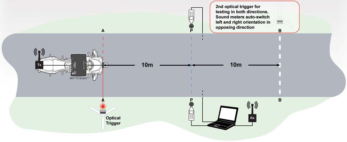 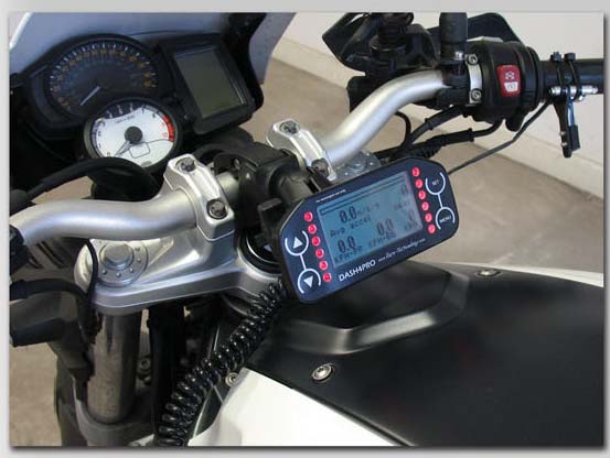 The DASH4PRO display, shown above mounted to the motorcycle's handlebars, is setup with the following data to assist the test rider: 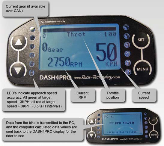 Data OutputsData from the bike is transmitted to the computer and is also displayed on the DASH4PRO for immediate feedback of test results; ensuring the rider can see if the test was run correctly. Constant speed test (L CRS)For the constant speed tests the gear and the test speed shall be identical to those used in the full throttle acceleration test previously performed. The test must be performed 3 times and the max result from left and right sound level meters from each test need to be averaged. Calculation of final resultThe final result is weighted combination of a constant speed test and a full throttle acceleration test. The results of the full throttle acceleration tests (L WOT) are used together with the results of constant speed tests (L CRS) to approximate partial load acceleration typical for urban driving. The corresponding target acceleration A urban is defined as: A urban = 1.28 * log(PMR) - 1.19
The formula for calculating the final result is: L urban= L WOT - (kp * (L WOT- L CRS))
Kp = 1 - (A urban/A WOT)
A WOT = the average acceleration achieved in the Wide Open Throttle test. Additional Sound Emission Provision Test (ASEP) Test procedure: When the front of the vehicle reaches AA; the throttle shall be fully engaged and held fully engaged until the rear of the vehicle reaches BB; The throttle shall then be returned as quickly as possible to the idle position. Test parameters
(max rated RPM - idle RPM) + Idle RPM
The selected gear shall be 2nd. If the 3rd gear satisfies requirements, 3rd shall also be used. If the 4th gear satisfies requirements, 4th shall also be used. 

Equipment used
(For motorcycles without throttle position available on CAN bus)
Equipment installation and setupThe SPEEDBOX R41 drive-by-noise test kit was designed to be universal system that is possible to be installed on all types of motorcycle and to have a very short installation time. If the motorcycle is equipped with a CAN bus then the installation is very simple only requiring 4 connections. a. 12v
b. Ground
c. CAN high
d. CAN low
If the motorcycle is not equipped with a CAN bus then the direct inputs must be used to acquire RPM and 100% throttle position. A 100% throttle switch to clamp on to the hand throttle is supplied with bracketry. This is designed to be adjusted so when 100% throttle is applied the switch is pressed as it contacts the brake lever or similar.
Equipment installation RPMFor sensing the RPM the box is supplied with a low level input. high level input and a VRS conditioning cable with built in pulse divider. Low level input specTriggering voltage requires a low input of< I v and a high input of >4v and JSv maximum. Suitable for connection directly to most ECU tacho outputs. Maximum input frequency> 300Hz. High level input specDesigned to connect directly to negative terminal of ignition coil. Can also fire from fuel injectors and from CD ignition systems VRS conditioning cableA VRS Signal Conditioner takes the unconditioned output from a Variable Reluctance Sensor (VRSJ, eg: an ABS wheel speed pickup, which is a noisy sine wave and outputs this as a clean square wave signal. lt can also divide the pulse frequency by a number between 2 and 255. Typically ABS sensors read a wheel with many slots, which gives a high frequency signal. By dividing the number of pulses the signal is better suited for use with a DLI. The computer is supplied with the kit and only requiring the modem and sound meters plugging into the USB ports. Tripods with reflective tape for the laser trigger on the bike needs positioning on each side of the test track.
How the equipment is used to perform the test Results and Performance software:The data is logged automatically in the performance monitor software which can be exported to excel or loaded into the Race Technology Analysis software. The following results in the green box below are produced from a fully editable script. The test must be performed 3 times and the max result from left and right sound level meters from each test need to be averaged. By right clicking in the green box and selecting copy you can simply and quickly copy the results from each test into a spreadsheet to calculate the specific results to each of the tests and motorcycles. 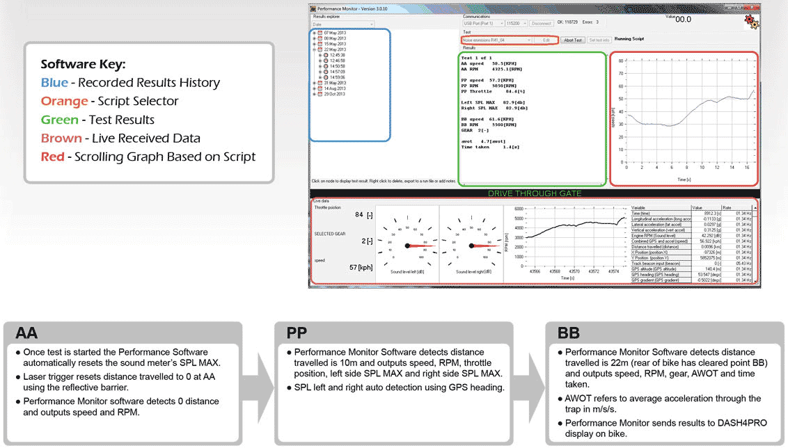
Scripting languageIntroductionPerformance editor comes with simple, yet powerful script editor. You can "program" the test to be done. Script editor features:
Description of the Drive-by-noise test script and how it works: 1) Open window to display text size 50 2) Start test 3) Display "Drive through gate" in window % means to ignore line and is used to input notes
****Start point****
4) Wait until distance is between 0 and 0.00 I 5) Create a name for the value of time at this point (StartTime) This will be used to calculate time taken at end of test
6) Create a name for the value of speed at this point (StartSpeed) This will be used to calculate average acceleration at end of test
7) Output results in performance monitor display screen Label, variable, decimal places, unit
****Mid point****
8) Wait until distance is more the 10 meters 9) Output results in performance monitor display screen Label, variable, decimal places, unit
****End point****
10) Wait until distance is more than 22 meters 11) Create a name of the value of time at this point 12) Create a name of the value of speed at this point 13) Output results in performance monitor display screen Label, variable, decimal places, unit
14) If heading is less than 0 output sound meter values left and right This enables automatic detection of left and right
15) Output average acceleration 16) Output time taken 17) End test The script can be made specific to a particular motorcycle or test to give pass or fail results based on it. Since the R41 final result is a combination of multiple tests this script is left universal outputting the required parameters for all test which then can be entered into a spreadsheet to avoid wasting valuable test time due to the wrong script being selected.
OpenPromptWindow 50
Start Test
Prompt "Drive through gate"
%*************Start point***********
Wait (VAR_0017>0 and VAR_0017<0.001)
Declare Start Time
Start Time= VAR_0001
Declare StartSpeed
StartSpeed = VAR_0015
Record Result "AA speed ",(VAR_0015),1,"KPH"
Record Result "AA RPM ",(VAR_0010),1,"RPM"
%************MID POINT************
Wait (VAR_0017>0.010)
Record Result "PP speed ",(VAR_0015),1,"KPH"
RecordR Result "PP RPM ",(VAR_0010),1."RPM"
Record Result "PP Throttle ",(VAR_3000),1,"%"
%************MID POINT************
Wait (VAR_0017>0.010)
RecordResult "PP speed ",(VAR_0015),1,"KPH"
RecordResult "PP RPM ",(VAR_0010),1,"RPM"
RecordResult "PP Throttle ",(VAR_3000),1,"%"
%**************END POINT************
Wait (VAR_0017>0.022)
Declare EndTime
EndTime = VAR_ 0001
Declare EndSpeed
EndSpeed = VAR_0015
RecordResult "BB speed ",{VAR_0015),1,"KPH"
RecordResult "BB RPM ",(VAR_0010),1,"RPM"
RecordResult "GEAR ",(VAR_2025),0."-"
lf(VAR_0403<0)
RecordResult "Left SPL MAX ",(VAR_7032),1,"db"
RecordResult "Right SPL MAX ",(VAR_7033),1,"db"
Else
RecordResult "Left SPL MAX ",(VAR_7033),1,"db"
RecordResult "Right SPL MAX ",(VAR_7032),1,"db"
%Endif
Record Result "awot ", ((((EndSpeed/3.6)^2)-((StartSpeed/3.6)^2)))/(44),1,"awot"
RecordResult "Time taken ",(EndTime- StartTime),1,"s"
Prompt "TEST PASS"
EndTest
Example Single Gear ResultsWot Speed Test
*** Result is the highest left or right averaged result
Constant Speed Test
*** Result is the highest left or right averaged result
*** L urban = (L WOT - (kp * (L WOT - L CRS))) |
||||||||||||||||||||||||||||||||||||||||||||||||||||||||||||||||||||||||||||||||||||||||||||||||||||||||||||||||||||||||||||||||||||||||||||||||||||||||||||||||