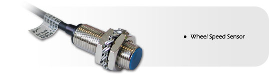
Wheel Speed Sensor
There are 2 types of wheel speed sensor we supply, the older black resin type, and the newer threaded body type. Both work in the same way and conform to the same specification. The main difference between the two is the mounting.
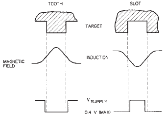
The "hall effect" wheel speed sensor is highly robust and designed specifically for high reliability automotive applications. It does not require a magnet to trigger it, just a moving metal "target", for example a bolt on the back of the brake disk.
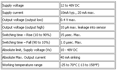
The sensor will function from a 12 to 24 VDC power supply.
Optimum sensor performance is dependent on the following variables which must be considered in combination:
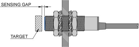
- Target material, geometry and speed
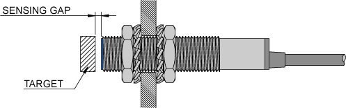
- Sensor target gap
- Ambient temperature
- Magnetic material in close proximity
Typical applications include:
Automotive and Heavy Duty Vehicle:
- Camshaft and crankshaft speed/position
- Transmission speed
- Tachometers
- Anti-skid/traction control
Key features are:
- Senses ferrous metal targets.
- Digital current sinking output (open collector)
- Better signal to noise ratio than variable reluctance sensors.
- Sensor electronically self adjusts to slight variations in run-out and variations in temperature.
- Fast operating speed – over 100 kHz
- EMI resistant
- Wide continuous operating temperature range.
Installation
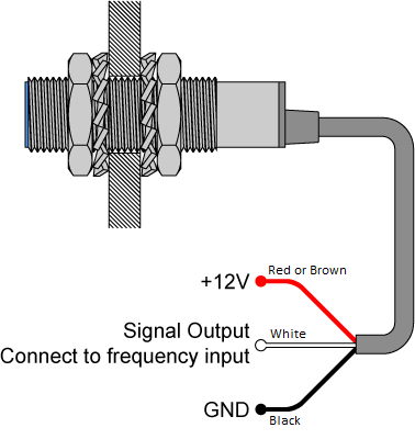
The sensor comes with 3 wires, the "red or brown" wire should be connected to a 12 - 24V DC supply voltage, the black wire should go to the ground connection and the white wire should go to one of the frequency inputs.
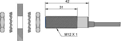
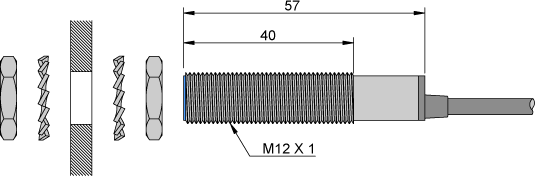
Mounting Dimensions Short Type
Mounting Dimensions Long Type
Target guidelines.
The Target Guidelines table provides basic parameters when an application is not restricted to a specific target.
Any target wheel that exceeds the following minimum specifications can be sensed over the entire temperature range of -40o to 150oC with any sensing gap up to .080 in. (2,0mm). This data is based on a 4 in (102mm) diameter wheel, rotating 10 to 3600 rpm.
Reference Target Dimensions
| Tooth Height: | .200 in. (5,06mm) min. |
| Tooth Width: | .100 in (2,54mm) min |
| Tooth Spacing: | .400 in. (10,16mm) |
| Target Thickness: | .250 in. (6,35) |
Connecting the sensor to a data logger DL1/DASH2
- Red or brown - Connect to +12v
- Black - Connect to ground (0v) on the DL1/DL2/DASH2
- White - Signal output from the sensor, this can be connected to any of the wheel speed, frequency or low level RPM inputs on the DL1/DASH2
If you are using the sensor as an RPM pickup, you must check that you have a big enough "target" to trigger from, most of our RPM inputs need at least a 1mS pulse to trigger from. Given a pulley diameter of "D" (in mm) and a maximum RPM, then the minimum target size (in mm) can be calculated from "RPM x D / 20000".
If you are using the sensor to drive a frequency input then the target can be smaller as these inputs are deigned to run at a higher maximum frequency, typically 0.5mS. The target size can be calculated from "RPM x D / 80000".