LC 2 Wideband Lambda Controller
Introduction
The LC 2 Digital Wideband O₂ Controller is a compact, high accuracy device used to measure lambda (λ) and air fuel ratio (AFR) in both road and motorsport applications. It provides a fast, stable output suitable for data logging, ECU calibration, and engine development work.
The LC 2 is fully compatible with Race Technology data loggers and display systems, allowing lambda or AFR values to be recorded and analysed alongside other engine parameters.
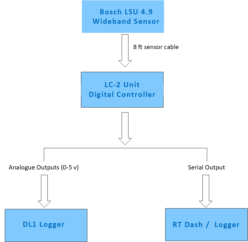
System Overview
System Components
| Component
| Description
|
| LC 2 Controller
| Digital wideband processor module
|
| Bosch LSU 4.9 Sensor
| High accuracy wideband oxygen sensor
|
| 8 ft Sensor Cable
| Connects sensor to controller
|
| Lambda Interface Cable
| Provides analogue + serial outputs
|
| Installation Hardware
| Mounting and wiring accessories
|
System Diagram
Wiring Information (Based on LC 2 Manual)
LC 2 Wiring Colour Table
| Wire Colour
| Function
| Notes
|
| Red
| +12 V Switched Power
| Must be fused; ignition switched
|
| Black
| Ground
| Connect to clean sensor ground
|
| Yellow
| Analogue Output 1
| Default: Lambda/AFR
|
| Brown
| Analogue Output 2
| User configurable
|
| White
| Serial TX
| Digital output
|
| Blue
| Heater Calibration Wire
| Used during initial setup only
|
LED Status Indicators (Summarised from Manual)
LED Behaviour Table
| LED Pattern
| Meaning
|
| Fast blinking
| Sensor heating / warm up
|
| Slow blinking
| Controller active, normal operation
|
| Solid on
| Calibration mode
|
| Rapid irregular blinking
| Sensor or wiring fault detected
|
Heater Calibration (Based on Manual)
The LC 2 requires a one time heater calibration when first installed or when replacing the sensor.
Calibration Summary
- Performed with the sensor in free air
- Blue wire is temporarily grounded to enter calibration mode
- LED will turn solid during calibration
- Calibration completes automatically
Sensor Installation
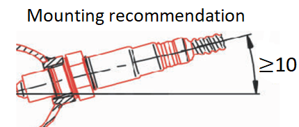
Sensor Placement Diagram
Installation Guidelines (Summarised from Manual)
- Install sensor at 10–12 o’clock to prevent condensation damage
- Minimum 24 inches downstream of turbocharger (if applicable)
- Avoid placing sensor at the extreme end of the exhaust
- Ensure no exhaust leaks upstream of the sensor
- Sensor must be powered whenever engine is running
Analogue Output Calibration
Typical Analogue Calibration Table
| Voltage (V)
| Lambda
| AFR (Gasoline)
|
| 0.00
| 0.65
| 9.7
|
| 1.00
| 0.78
| 11.5
|
| 2.00
| 0.92
| 13.5
|
| 3.00
| 1.05
| 15.4
|
| 4.00
| 1.20
| 17.6
|
| 5.00
| 1.36
| 20.0+
|
These values can be entered directly into the Race Technology software.
Troubleshooting
Common Issues and Solutions
| Issue
| Possible Cause
| Solution
|
| Unstable readings
| Poor grounding
| Check ground points
|
| Incorrect AFR
| Wrong calibration
| Re enter voltage table
|
| Sensor error
| Sensor contamination
| Inspect or replace sensor
|
| No serial data
| Wiring error
| Check TX/RX connections
|
| LED flashing rapidly
| Sensor fault
| Inspect wiring or replace sensor
|
Further Information
For detailed installation and configuration instructions, refer to the Innovate Motorsports LC 2 documentation.
For integration with Race Technology products, see the DL1, DASH, and ECU interface manuals.