Thermocouple Amplifier
| Exhaust Gas Temperature Kit
| MK2
| MK1
|
| 
| 
|
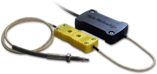
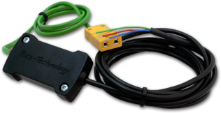
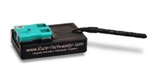
The thermocouple amplifier is designed and built by Race Technology and is ideal for autosport and automotive testing applications. There are two versions of the amplifier available (for both MK2 and MK1), which cover 2 common temperature ranges:
- -100 to 210oC. This is ideal for measuring fluid temperatures in the engine, for example oil and water.
- -100 to 1150oC. Typically this is used for exhaust temperature measurement.
Note that the temperature range must be specified at the time of ordering, it cannot be subsequently changed.
In either case the thermocouple amplifier is powered from a single 5v supply, and outputs a 0-5v signal which makes it ideal for direction connection to any of our loggers. There is a standard miniature k-type thermocouple connector one end, and a flying lead to connect to the logger on the other end. The electronics include the cold junction compensation for the thermocouple.
Technical Data
| Supply voltage
| 5 ±5% V
|
| Output voltage
| 0-5 V
|
| Operating temperature range
| 0-70°C
|
| Current consumption
| 5 mA
|
| Typical accuracy
| ±1% of reading + 2 °C
|
| Temperature Range
| -100 - 1150 oC
-100 - 210 oC
|
| Input connector
| Miniature K-type
|
| Thermocouple
| Standard K-type
|
| Output connector
| Wire ended flying lead
|
Typical calibration data from 7 sample units
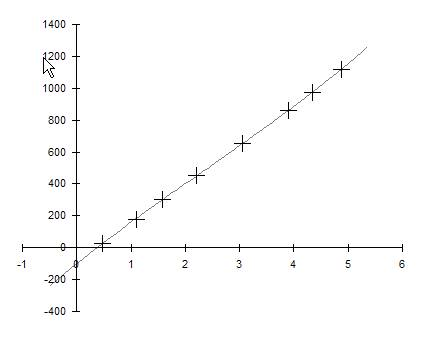
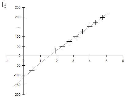
These tests were carried out on 7 units taken from stock and randomly checked using externally calibrated equipment. Note that if more accurate calibration is required for a particular application then it is best to do so with the actual thermocouple and then adjust the final value in the calibration (“–102.05” for the high range) and (“–112.48” for the low range) as required.
| Low range amplifier
|
| Set temp 25oC
| Set temp 200oC
|
| 24.5
| 201.1
|
| 24.7
| 201.4
|
| 26
| 204.2
|
| 23.9
| 201.9
|
| 26.6
| 203.9
|
| 25
| 202.6
|
| 25.5
| 204.2
|
| High range amplifier
|
| Set temp 21oC
| Set temp 1123oC
|
| 21.7
| 1114.5
|
| 18.9
| 1117.5
|
| 21
| 1118.8
|
| 18.9
| 1116.5
|
| 19
| 1114.5
|
| 20
| 1115.2
|
| 18.5
| 1118.8
|
Cold junction compensation
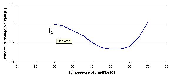
The electronics in the amplifier also compensate for so called “cold junction” effects, this is an important function of the amplifier electronics. Simply, this measures the temperate of the amplifier electronics and corrects the output signal accordingly. Note that if the user wants to reproduce these results you must heat and cool the whole amplifier assembly at the same time, any temperature differentials in the unit will cause errors.
High range amplifier calibration
Low range amplifier calibration
Installation
There are 3 leads that come from the sensor:
| Exhaust Gas Temperature Kit
|

|
- the red lead should be attached to the +5v supply from the Data Logging Units
- the blue lead should be connected to the ground connection on the Data Logging Units
- the green lead should be connected to an analogue input.
|
| MK2
|

|
- the red lead should be attached to the +5v supply from the Data Logging Units
- the blue lead should be connected to the ground connection on the Data Logging Units
- the green lead should be connected to an analogue input.
|
| MK1
|

|
- the red lead should be attached to the +5v supply from the Data Logging Units
- the black lead should be connected to the ground connection on the Data Logging Units
- the white lead should be connected to an analogue input.
|
Note that whilst the thermocouple tip temperature is obviously up to the full 1000oC of the exhaust, the amplifier is only rated up to 70oC and so it must be mounted in a location that limits its temperature.


