|
Call me back |
|

You are here: Website » Knowledge base
|
LapSimulation / ConfiguringConfiguring the vehicle simulation
All the simulation configuration is within the single “Simulation options” menu. Note that all the options set for the simulation are:
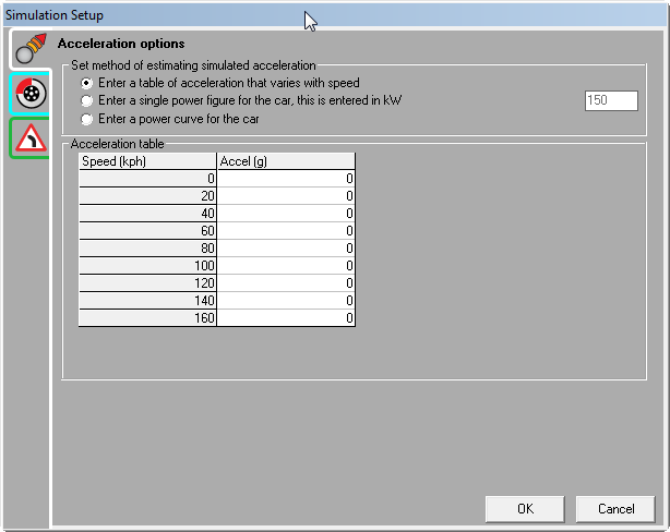
To open "Simulation Setup" window go to Data > Edit default simulation options. 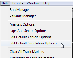
Acceleration options
 Note that whatever information is entered in the acceleration options, the absolute maximum rate that the vehicle can acceleration is also limited by the data that is entered in the Braking options. For example, if for the acceleration options entered the computer calculates that the vehicle could accelerate at 1.35g at a speed of 20kph, but at 20kph the maximum braking force is 1.2g, then the acceleration would be estimated as 1.2g and that this was limited by traction rather than engine performance.
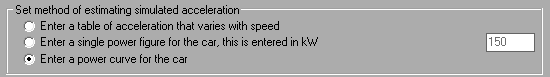
 This is the simplest method available for estimating the maximum rate of acceleration. This simply consists of an acceleration that the vehicle can achieve as a function of speed. For example at low speeds high rate of acceleration are possible, as the speed increases the maximum rate of acceleration reduces, until at the vehicles maximum speed no acceleration is possible. The rates of acceleration are entered into the table, and are also shown on the graph. To edit a value in a cell, you left click on it. To copy or paste the whole table to or from excel you can right click on the table.
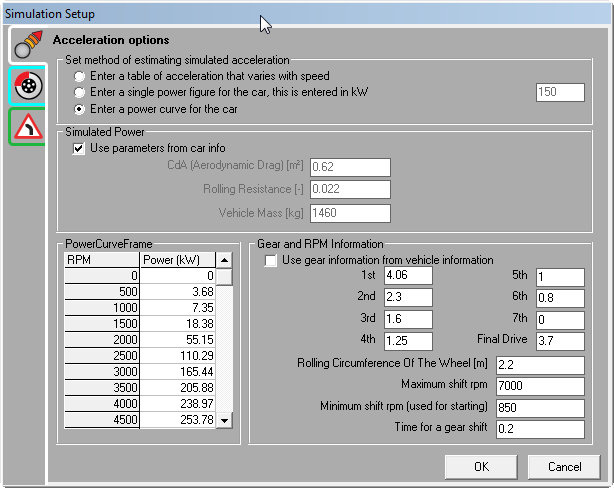
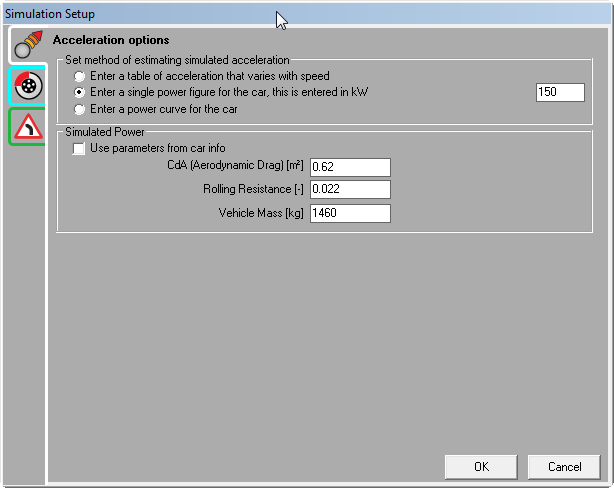 This mode requires more information to be entered about the car, but is generally a little more accurate – but most importantly allows the user to test the effect on lap times of increasing the vehicles power, albeit in a very simple way. To use this mode the user must enter 3 parameters onto the form:
Of these parameters, the vehicles weight is generally known, or can be found in the cars technical data. In the case of the weight, this is the weight as it is raced, and should include an allowance for the driver and fuel etc. The other 2 parameters, CdA and Rolling resistance can be found in a number of ways:
Once this information has been entered then the computer knows everything that is required to calculate how quickly the car can accelerate at any speed. Using this mode it’s very simple to see the effect on lap times of increased power output.
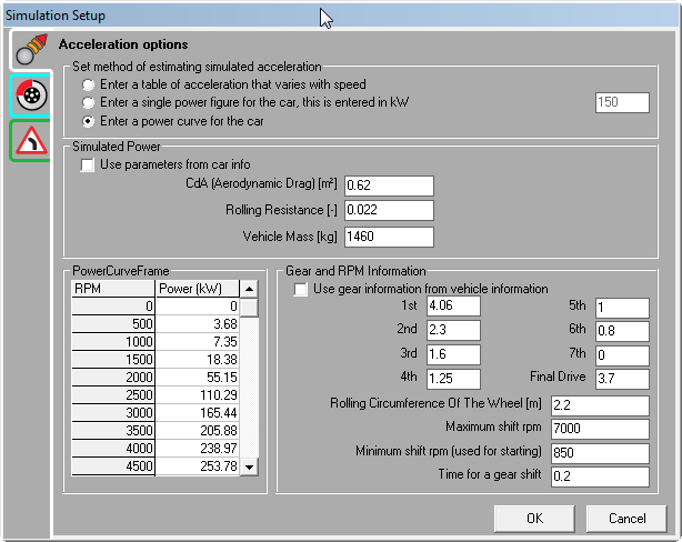 This is the most accurate and comprehensive simulation mode, but it also requires the most information to be entered about the car. It requires the following information to be known:
This is exactly the same as for the “single power” case (2nd option) and is described above. In addition this mode requires:
Given all this information, the computer can generate more accurate estimate for acceleration times of the vehicle out of the corners and simulate the engines RPM and what gear is recommended at any particular point. Note that when reviewing simulated RPM and gear information, they are only given when the vehicle is accelerating. During braking “0” is shown.
Braking optionsThere are 2 options for specifying how rapidly the vehicle can brake, or decelerate: 1. Enter a single figure for braking grip 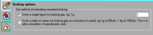 The first option is the simplest, in this case the user simply gives a fixed level of grip that is valid at all speeds. This is a good approximation for cars without significant aerodynamic aids (wings and large splitters etc). For a typical road saloon car with road tyres this figure is “about 1g”, for a race car with slicks and no significant down force this is “about 1.3g”. By looking at old race data then more accurate estimations can be made, however these figures give a good starting point. 2. Enter a table of values for braking grip as a function of speed 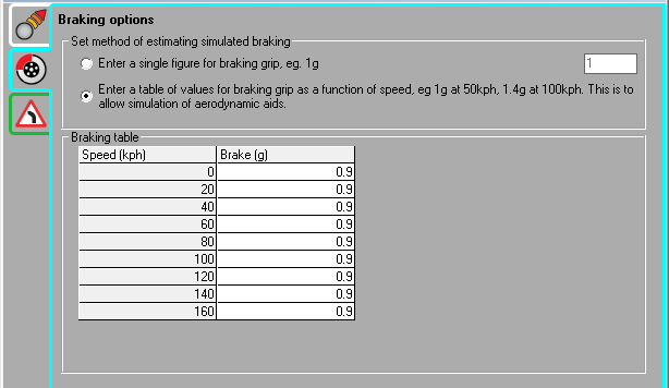 Using this mode of braking simulation, it is possible to have the maximum grip vary with speed. This is essential for simulating cars with large wings or splitters that generate more down force at high speeds. With such aids the vehicle is “pushed down” onto the track at high speeds which increases the grip and makes harder braking possible. To manually edit a value in a cell, you left click on it. To copy or paste the whole table to or from excel you can right click on the table.
Cornering optionsThere are 2 options for specifying how rapidly the vehicle can take corners: 1. Enter a single figure for braking grip 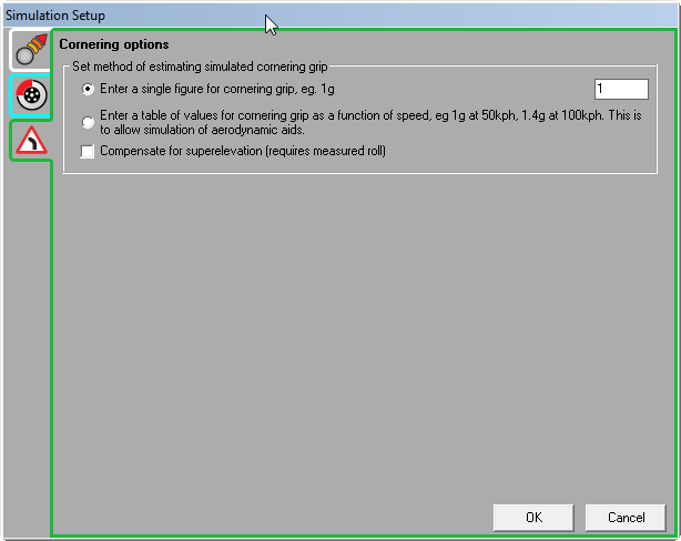
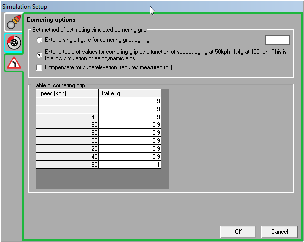
Compensate for superelevation (requires measured roll) When superelevation is enabled, the roll angle of the vehicle is used by the calculations to be the superelevation angle of the road. As such it is important that the inertial sensor is correctly zeroed on a flat surface and that the vehicle is driven slowly around the desired path so as not to induce any extra roll on the vehicle from lateral g-force. |