Configuring the CAN reception
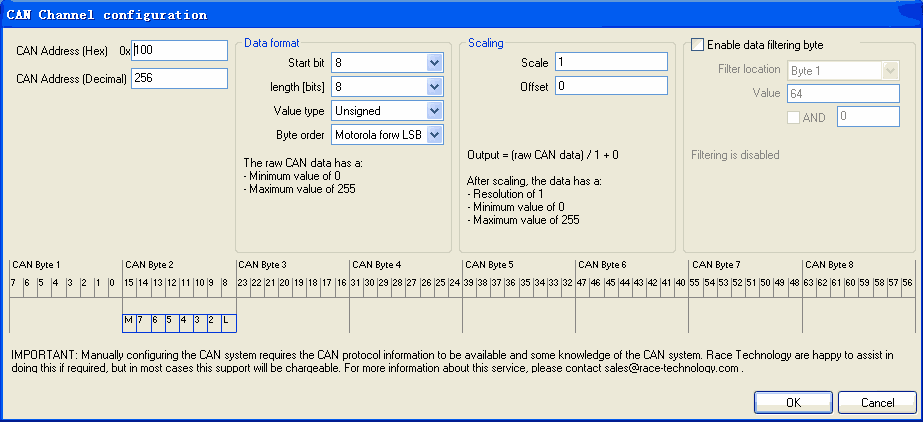
For each channel of received data the CAN bus must be configured. This is used to set up where in the CAN datastream the data is decoded from and how the data bytes are arranged. Simple scaling and offset can be applied in here to get the received values in to user units.
- CAN Address (Hex) and (Decimal)
The address can be set either in hex or in decimal.
Here the start bit, data length, value type and byte order are set. These factors together describe how the data is decoded from the CAN data.
There are six different methods which can be used to describe the CAN byte order, these have an effect on which bit the start bit refers to, as some point to the least significant bit (lsb) and some to the most significant bit (msb). For more information on how these systems work look
here.
The data format is always shown graphically at the bottom of the screen, this can be invaluable for checking that the data format is correct.
The value type can be set to Unsigned or Signed. If the value is signed then the data is treated as being encoded using two’s complement arithmetic. This affects the input range of the data and must be set according to the specification in the output configuration of the device the data is being read from . It does not relate whether or not the output data is signed. For example. The input data could be unsigned with an input range of 0-127 but have an offset of -127 applied giving an output range of -127 to 128. The data is still unsigned when read from the CAN interface.
The maximum and minimum values of the decoded data are shown just underneath where the data format is set.
When the data has been decoded it can have a scale and offset applied to it. This is usually done to convert the raw CAN values in to standard units for storage. When stored internally in the Race Technology data format channels should be scaled to the following types.
| Channel type | Storage unit | resolution | Min value | Max value |
|---|
| Angles | degrees | 0.1degree | -3276.8 | 3276.7 |
| Temperatures | degrees C | 0.1 degree | -3276.8 | 3276.7 |
| Auxilary | 1 | 0.1 | -3276.8 | 3276.7 |
| Pressure* | mbar | 1mbar | 0 | 65535 |
| Time | ms | 1ms 0 | 65535 |
| Analogue | mV | 1mV | 0 | 65.535V |
For further information on other specific channels please see the detailed channel information here.
In some CAN data streams messages are only valid when a particular byte or bit has a certain value. For example the first byte in a message might be used to say which cylinder exhaust temperature data relates to. By applying a filter the message can be decoded when these conditions are true.
This is the byte which is used for the filtering, filtering is only possible based on a maximum of one byte of data
This is the value which the byte must have
This is used to filter the byte so that only certain bits are included in the calculations. The value of the byte when logically ANDed with this value must equal the the value set.
Example:
A data validity bit exists in bit 7 of byte 1, the data is only valid when this bit is set.
Filter location = Byte 1
Value = 10000000b = 256
Value must be ANDed with 10000000

