Monitoring Variables
- 5.2 View Serial variables
- 8.3 View CAN variables
- 8.4 View CAN variables at a different bit rate
These menu item is used to ensure that data transmitted by the Data Logger is being properly received by the DASH4PRO FD and that this data is being decoded, converted and filtered properly.
Monitoring Serial variables
1. Enter menu display mode by pressing the MENU button.
2. Use the UP/DOWN buttons and navigate to menu item 5 Test DASH4PRO in the main menu. Press SET button to enter the sub menu.
3. Use the UP/DOWN buttons to navigate to menu item 5.2 View Serial Variables and press the SET button to open the serial variables screen.
4. You can leave the screen at any time by pressing any of the buttons.
This screen is the DASH4PRO FD equivalent of the Race Technology Live Monitor software. The screen displays the following information:
In the above example the name of the variable is given as speed
A unique variable index that is used to refer to this variable in all Race Technology products
Approximate rate at which information regarding this variable is received by the DASH4PRO FD in Hertz (Hz) – i.e. the rate at which messages containing information on this variable are being sent by the Data Logger to the DASH4PRO FD
This is the value contained in messages sent by the Data Logger – i.e. the decoded value. On the Live Monitor software this value would come under native units. In the given example the value of speed is reported in km per hour (kph)
This is the value of the variable as shown on a data display screen – i.e. the input value is converted to user specified units and filtered using a rate of change filter and a smoothing filter. On the Lite Monitor software this value would come under user units. In the given example the value of speed is reported in miles per hour (mph)
Note: Some variable information, such as gear and lap timing information are calculated on the DASH4PRO FD itself. Therefore, the frequency or rate information for these variables is not displayed.
Monitoring CAN varialbes
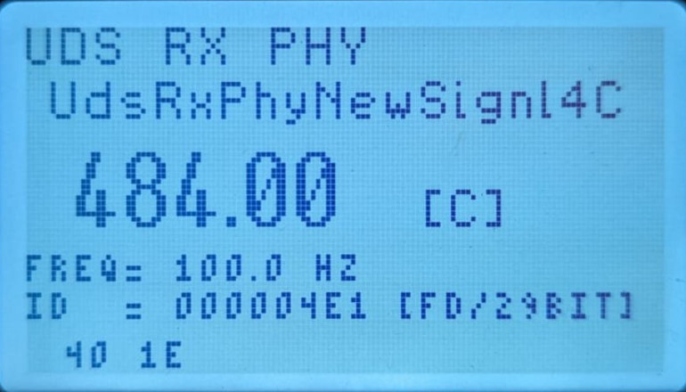
Menu “8.3 View CAN variables” can be used to view all DBC variables of the referenced DBC file(s). Those variable data will be shown at the current baud rate which you set using the DASH4PRO FD configuration software.
If the baud rate is matched with the connected CAN bus, continuously increasing count will be seen on the first screen. Use UP and DOWN buttons to scroll through the variables.
To add DBC variable data to your configuration:
- Add DBC file(s) using Var and CAN manager application.
- Added file(s) will be instantly available under the CAN node of the DASH4PRO FD variable tree.
- Write your configuration to the device; all CAN variable information of referenced DBC files will also be sent to the device.

|
| 8.3 View CAN variables
|
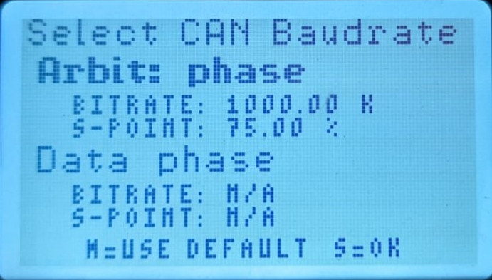
The baud rate of "CAN variables" and "raw CAN data" can be changed using the following menu items:
- baud rate of "CAN variables" - 8.4 View CAN variables at a different bit rate
- baud rate of "raw CAN data" - 8.2 View raw CAN data at a different bit rate
When selected, the count screen appear as in Menu 8.3 along with scrollable CAN messages.

|
| Setting a different bit rate for CAN variables/raw CAN data
|
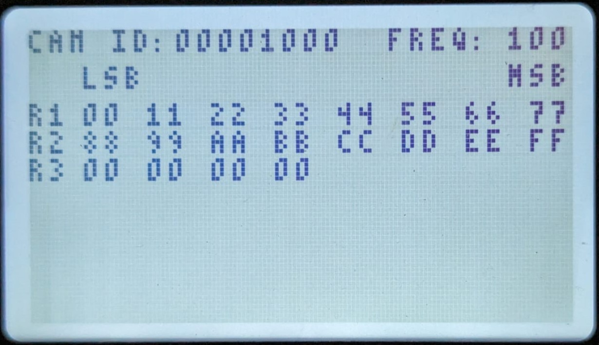
Menu 8.1 can be used to view the raw CAN data:

|
| 8.1 View raw CAN data
|


