Compact Dual Antenna INS Installation
The SPEEDBOX base unit should be mounted inside the vehicle. The base unit can be mounted in any orientation for the SPEEDBOX-INS, since the INS system takes all inertial measurements from the antenna assembly. The base unit should be isolated from excessive vibration, and the supplied power cable should be connected to a suitable power supply.
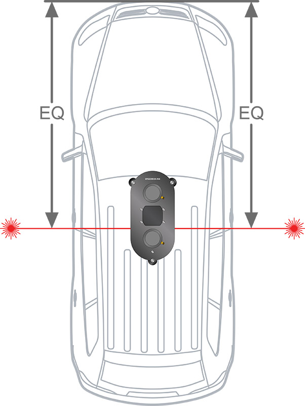
IMPORTANT!!! The antenna assembly should then be mounted on the roof of the vehicle in the correct orientation. Lasers are used to achieve accurate alignment on the vehicle. The unit should be mounted on the stiffest part of the roof to eliminate vibration, typically this is on the curve at the front just above the windscreen or side of the roof. Additionally the unit should be mounted at no more than 20 degrees from the horizontal.
INS Dual Compact Antenna Installation:
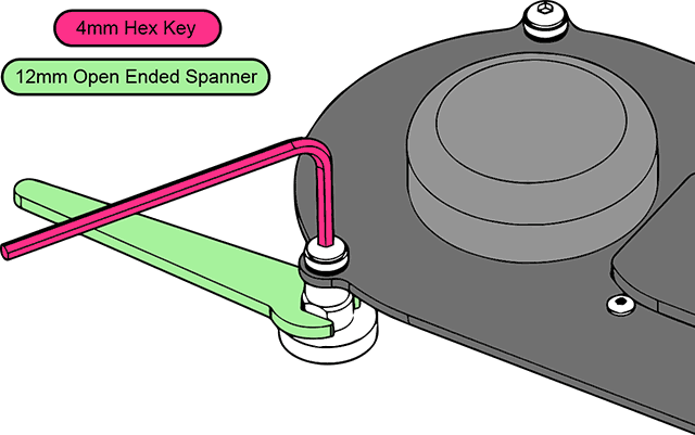
The INS Compact Dual Antenna system features low-compliance magnetic feet, further improving system measurements by providing a more rigid mounting solution. The magnetic feet must be adjusted to fit against the curved roof of a vehicle to achieve maximum mounting force. To do this the angle must be adjusted using the cup and cone washers. A 12mm open ended spanner and a 4mm hex key are required to do this.
Loosen the hex bolts at the top of the two front legs using a 12mm open-ended spanner to hold the leg, and a 4mm hex key to loosen the hex bolt.
Place the INS Compact Dual Antenna in place on the roof of the vehicle. Placing accurately using the lasers.
Tighten the hex bolts at the top of the two front legs.
Check rear magnet contact with vehicle roof, if required loosen and tighten this leg to fine tune alignment (using lasers) on vehicle and magnet contact.
Once the base unit and antenna assembly have been correctly fitted, they must be connected using the supplied cable. This cable contains both the data cable for the IMU and the GPS antenna cables. The routeing of the cable from the base unit to the antenna assembly should avoid as far as possible any sources of RF interference, in particular components of the vehicle ignition system, telemetry or radio systems, and in some cases video camera systems. Passing the cable through an open window is recommended.
The data cable from the IMU to the SPEEDBOX base unit connects to the antenna assembly at one end, and to the “INS Sensor” port of the SPEEDBOX base unit at the other end. Note that the data cable must be connected prior to switching on the INS system in order for the antenna assembly to be correctly detected – if the power is supplied prior to plugging in the IMU cable then the SPEEDBOX will flash an error code to indicate that the IMU is not detected. In this case it is simply necessary to power-cycle the unit after plugging in the IMU cable. The GPS antenna cables from the INS antenna assembly to the SPEEDBOX unit are labelled on the heatshrink and correspond with the labels on the SPEEDBOX unit’s SMA connections.
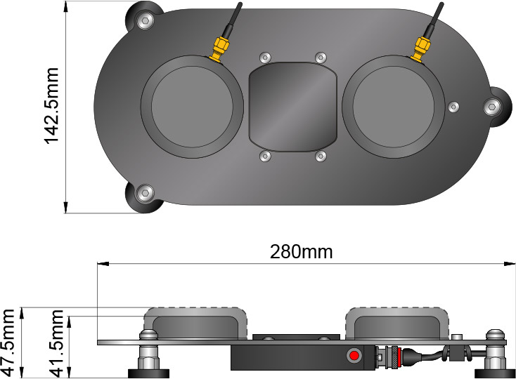
Antenna Unit Dimensions:
The Compact Dual Antenna has two options for the antennas, the larger dual frequency GNSS antennas, and the smaller GPS only antennas. The choice of antennas is dependent on the application.


