Link G4 / Vi-PEC V44, V88 & i-serial (RS232)
Compatibility
- Link G4
- Vi-PEC V44
- Vi-PEC V88
- i-serial
Configuration
The ECU with firmware version 4.2.0 onwards must be set up to output the required data at 57.6 kbaud, the DataStream mode also needs to be set to "off". After these settings have been configured turn the power off the ECU and back on again. Changes to baud rate and DataStream only take effect if this is done.
Connections
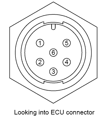
These ECU should be connected via serial (RS232) connections:
You will also need a cable from the ECU manufacturer in order to connect the Race Technology interface to the data output of the ECU.
| Pin
| Colour
| Function
|
| 1
| Brown
| Ground
|
| 2
| Blue
| N/A
|
| 3
| White
| CAN H
|
| 4
| Green
| CAN L
|
| 5
| Yellow
| ECU RS232 TX
|
| 6
| Gray
| ECU RS232 RX
|
Data Channel Listing
The following configuration is used with the ECU interface:
| ECU Message Name
| Race Technology Data Channel
| Resolution of Data
|
| RPM
| RPM (Engine RPM)
| 25 rpm
|
| ECT
| Coolant temp (temperature 8)
| 1 oC
|
| IAT
| Ambient air temp (temperature 1)
| 1 oC
|
| ECU temperature
| ECU temp (temperature 16)
| 1 oC
|
| AN Temp 1
| Exhaust 1 temp (temperature 17)
| 1 oC
|
| AN Temp 2
| Exhaust 2 temp (temperature 18)
| 1 oC
|
| AN Temp 3
| Exhaust 3 temp (temperature 19)
| 1 oC
|
| AN Temp 4
| Exhaust 4 temp (temperature 20)
| 1 oC
|
| AN Volt1
| Fuel inj 1 cut (aux 14)
| 0.1
|
| AN Volt2
| Fuel inj 2 cut (aux 15)
| 0.1
|
| AN Volt3
| Fuel inj 3 cut (aux 16)
| 0.1
|
| AN Volt4
| Fuel inj 4 cut (aux 17)
| 0.1
|
| AN Volt5
| Fuel inj 5 cut (aux 18)
| 0.1
|
| AN Volt6
| Fuel inj 6 cut (aux 19)
| 0.1
|
| AN Volt7
| Fuel inj 7 cut (aux 20)
| 0.1
|
| AN Volt8
| Fuel inj 8 cut (aux 21)
| 0.1
|
| AN Volt9
| Auxiliary 1 (aux 26)
| 0.1
|
| AN Volt10
| Auxiliary 2 (aux 27)
| 0.1
|
| AN Volt11
| Auxiliary 3 (aux 28)
| 0.1
|
| MAP
| Boost pressure (pressure 5)
| 1 mbar
|
| AIP
| Ambient air pressure (pressure 1)
| 1 mbar
|
| Battery voltage
| Battery voltage (misc 3)
| 0.01v
|
| Throttle position
| Throttle position (aux 1)
| 0.1%
|
| Injector duty cycle
| Fuel inj 1 PW (aux 6)
| 0.1%
|
| Inj duty cycle (stg)
| Fuel inj 2 PW (aux 7)
| 0.1%
|
| Injector time
| Fuel inj 1 PW on (measured time 1)
| 1ms
|
| Dwell time
| Fuel inj 2 PW on (measured time 2)
| 1ms
|
| Injector angle
| Throttle angle (angle 1)
| 1o
|
| Ignition angle
| Ignition angle (angle 2)
| 0.1o
|
| DI 1 frequency
| EGR freq (frequency 2)
| 0.1 Hz
|
| DI 2 frequency
| ISBV freq (frequency 3)
| 0.1 Hz
|
| DI 3 frequency
| Nitrous solenoid freq (frequency 4)
| 0.1 Hz
|
Not all channels listed in the table above may be available from your ECU. The available data channels vary with the vehicle model, year of manufacture & connected sensors.


